Rear fog light icon in switch for VWs (euroswitch)
These are directions on how to get the rear fog light icon in your euro switch to light up when you turn on the rear fog light.
Standard Disclaimer: I do not make any guarantees that this procedure will work for you. Neither can I be held accountable for any damage that happens to your switch during these steps.
- Open the switch by gently popping open the 4 tabs.

The other two tabs are on the other side in the picture.
- Once you have popped all 4 tabs, gently pull apart the two sides of the switch. They should come apart 3/8 of an inch and stop.
Don't try to force them apart. Rotate the two halves clockwise with respect to each other about 45 degrees and you should feel the stem of the switch come apart. At this point you can pull the two pieces apart completely. This is how one side looks after its separated.

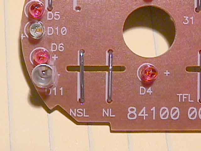
If the circuit board is of much lighter color than above and has no component marking on it then check out this link.
- Look at the lower left hand corner. This is where your LED and connecting pin will go.
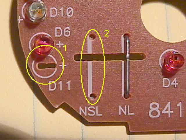
1 is where the LED will go and 2 is where you have to solder a wire so that the circuit board makes contact with the switch contacts.
- Looking at the printed side of the circuit board, solder the LED at location 1 and solder your wire at location 2.

Pay attention to the polarity of the LED. There is a "+" sign on the silkscreen side to show which side should be +. For the wire I used the smallest paper clip I could find. Its the right thickness and stiffness for this contact. Use pliers to shape the wire properly.
- You may also need to adjust a couple of resistors shown in circle 3 above. The combined resistance of these two should be close to 470 ohms. If you use an LED whose operating voltage is 1.8 ~ 2.4 volts then you don't need to change these resistors. Anything outside that range and you may have to tweak these two resistors to make sure that the red LED goes off when you new LED comes on. I decided to use a blue LED which was a bad idea. Its rated at 3.8+ volts and simply adjusting the resistors wouldn't quite do the trick. I had to change the circuit around to make it work.
- This is how it looked after soldering the LED and wire in place.
Note that if you use a 5mm LED, you'll have to file it a bit to get it to fit. So don't get an LED bigger than 3mm.

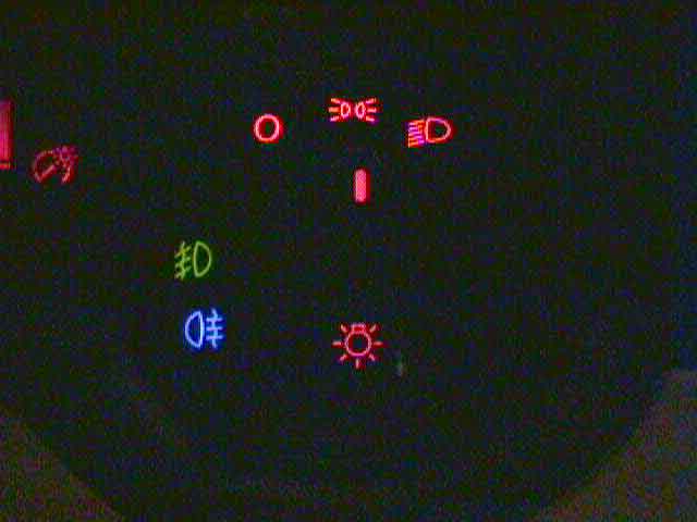
- And finally here is the finished product.
Here is a better picture of a yellow LED compliments of BORA_WE.

If you have any questions feel free to send me e-mail.